Propeller shafts or in marine terminology also known as tail shafts are commonly found on the ship’s aft segment behind the ship’s propulsion. It is a round metal fixture attached to rotate, connect, and mediates force from one component to another.
The tail shaft is a part of the propulsion system not only in marine but also in automotive and aviation. In general, it serves as a connection between the engine and the drive unit, for boats the drive unit is called the propeller.
A propeller is a fan-like structure situated underwater and attached to the vessel shafts. These propellers have various types and forms but the main principle is to have twisted blades that when rotated cause lateral motion on the plane where it is being spun. This lateral motion is therefore seen as the ship’s movement either ahead or astern.
The connection built by the tail shaft between the main engine and the propeller also transmits the power (speed and torque) produced by the main engine to the ship’s propellers.
Precisely, the energy coming from the main engine whether diesel or electric that is manifested on its flywheel is connected to a marine gearbox (if equipped) or directly to the propeller shafting, depending on if an intermediate shaft is needed or only the propeller shaft is installed.
The energy held into the driving shaft is delivered to the propeller where it translates the rotating motion to the forward and reverse movement of the ship’s hull.
On a broad understanding, the connection between the engine to the shaft and to the propeller acting as a single unit forms a system called propulsion. As you can see, the design varies to fit the vessel conditions for example vessel size and type.
The propulsion system adapts to the vessel’s needs. Manufacturers of such take worth considering the length between the ship engine and the propeller. The longer space between the said components more additional fittings/ parts are installed to ensure the firmness and efficiency of the system.
The length between the engine and propeller differs per vessel type. As we all commonly know the propellers are always fitted on the ship’s rearrest portion but the engine position can either be in the middle or later part of the ship.
The position is determined during ship construction by naval architects who plan the vessel’s general arrangement in line with its stability. Vessel general arrangement is a layout where the various equipment (generators, main engine, boilers, steering gear and etc.) aboard is identified/ placed around the ship.
On the other hand, ship stability focuses the weight distribution around the ship (machinery, cargo, and structures) to know the behavior of the ship and how it will react at light load and full load conditions, on calm and heavy seas.
The stability focuses on determining the ship’s stresses acting upon the hull and identifying dynamic points such as the center of gravity, the center of buoyancy, and the metacenter of the ship.
For instance, container ships versus bulk carriers. Container ships do have superstructures on the amidship were at the bottom of this structure, the ship’s heart – the main engine is placed while bulk carriers have theirs installed at the aft portion.
This difference presents different arrangement problems the system has to face which is why intermediate shafts, intermediate bearings, thrust blocks and etc. are introduced. The items mentioned will be discussed later on
What are the types of propeller shafts?
In various ways, the propeller shaft is connected to the main engine, depending on it the tail shaft can be classified. Three types used are flanged connected, tapered shafts, and muff coupling.
Flanged connected propeller shafts are shafts having a rim around its tip used to connect to another shaft with the same lip size and a number of holes. The holes are flawlessly aligned and fastened with bolts. Reliant to the tail shaft size and application, bolt sizes and material composition are assigned.
Tapered shafts are shafts having tapered ends or decreasing diameters. On those reduced diameter tips, a shaft crown is installed. This shaft crown is fixed mechanically along the shaft body with a key on its center to ensure the crown won’t slip as it rotates. The crown is coupled with stud bolts to the main engine driving shaft or gearbox flange.
Muff Coupling is a type of shaft coupling where two perfectly aligned shafts are enveloped by a muff or sleeve. This sleeve consists of an outer and inner conical jacket. The outer jacket is pushed parallel and hydraulically so that it will compress the inner sleeve that is tapered and slightly larger than the shaft diameter.
Once the sleeves are compressed at the manufacturer’s recommended pressure, it is then released. The muff sleeves form a strong couple between the two shafts.
Main Components Of Marine Propeller Shaft Arrangement
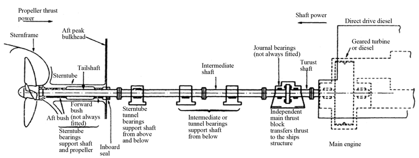
The shown diagram is an almost complete illustration of a ship’s propulsion system. The purpose of the items presented above will be discussed shortly below from rightmost to leftmost.
The thrust shaft is a propulsion shaft portion where it is supported by the thrust block. This shaft connects the driving engine to the intermediate shaft. The sole purpose of this shaft is to deliver the rotating motion of the engine to the intermediate shaft.

Propeller Shaft Thrust Block
A thrust block is also a form of bearing mounted steadily on the ship structure to resist the thrust produced by the propeller shaft. This resistance transmits the force to the ship’s hull and creates movement. The block holds and lubricates the thrust shaft while it rotates. These blocks are also referred to as thrust bearings or thrust boxes. The oil lubricating the thrust shaft is enclosed by the thrust block and is sealed by two labyrinth rings known as forward and aft end seals.
Journal bearings are metal rings that are surfaced between the rotation shaft and the thrust block. These bearings center the shaft inside the thrust block. The support provided by the journal bearings maintains the shaft orientation while it spins inside the hollow portion of the block where lubricating oil is encased.
Intermediate shaft
Intermediate shaft quantity and length are reliant on the ship’s length. For ships having wider space between the engine and propeller the intermediate shaft length increases and its purpose is to link the propeller shaft to the thrust shaft.
Intermediate bearings support the intermediate shaft on its vital points to keep it aligned and allow it to move freely as it rotates on its axis. The longer the intermediate shaft the more bearings are placed to hold.
Stern tube tunnel bearing
Stern tube tunnel bearing like the first two mentioned bearings supports the shaft of the propulsion system but mainly concerns the last shaft segment called the propeller shaft. These tunnel bearings are found adjacent to the rigidity tube where the propeller shaft exits the ship spaces underwater.
Inboard seals and outboard seals are closure designs to prevent seawater ingress to the ships’ hulls and oil leakage to the sea. These seals provide a barrier between two medians (water and oil) to mix. These seals are very important with regards to ships’ stern tube lubrication systems. As the name suggests, inboard seals barricades oil or water to enter the ship spaces. On the other hand, outboard seals prevent the loss of oil by spillage to the sea. Sealing arrangements will be elaborated on later in this article.
The stern tube is the part of the vessel’s hull where it houses the bearings and propeller shaft going out from the ship space to the underwater. Sometimes called the rigidity tube this housing offers passage for the propeller shaft cooling and lubrication arrangement.
Tail Shaft
The tail shaft or the propeller shaft is where the propeller is attached to the end. This shaft is majorly placed underwater and receives primarily the thrust created by the spinning propeller.
A strut is support attached to the ship’s hull underwater and holds the tail shaft as it is being propelled. They are also fitted with a bushing bearing which keeps the tail shaft alignment.
Propeller as discussed at the beginning is wheel-like structures fitted with warped blades that are attached to the tail shaft. This structure provides push or pull movement to the ship hull as it is processed by the propulsion system.
The Stern Tube Sealing Arrangement
The sealing arrangement of the stern tube varies with its lubrication type. the stern tube can either be hydro-lubricated or oil lubricated.
Hydro-lubricated stern tube systems have bushing bearings installed between their tail shaft and stern tube. The bushing bearings have grooves or flutes around them where it allows a direction of seawater to flow. This flow of seawater reduces the friction between the bearing and the propeller shaft as the shaft rotates on it.
The system introduces a pump suctioning from the sea chest to deliver the seawater to the shaft bearings where it passes continuously until it escapes back to the sea. The nonstop flow of seawater provides cooling to protect bearings from premature wear as the shaft is rotated especially at high RPMs.
Oil-lubricated stern tube system uses biodegradable oils as cooling and lubricating element. This system utilizes an oil reservoir circulated by a pump to create a cycle. The oil goes in and out of the stern tube conservatively.
The oil is being conserved to prevent oil spillage to the sea. In any unfortunate event, the oil is biodegradable to prevent harm to marine life. The oil has the same function as seawater in the hydro-lube system protecting the stern tube bearing from premature wear.
The system dumps the heat collected by the oil thru a heat exchanger which is connected to the seawater system. In any case, the heat collected is transferred from the shaft to the stern tube oil to the seawater where it is released back into the vast ocean.
Generally, there are three types of stern tube sealing arrangements. These are mechanical face seals, packing-type seals, and lip seals. Like what we commonly see on pumps’ mechanical seals and packing glands, mechanical face seals and pacing-type seals are quite similar.
Mechanical face seals or dripless face seals have rubber below, a carbon/graphite ring, and a rotating flange. The bellow’s end wraps around the stern tube opening while the opposite end is equipped with a graphite ring. The bellow also acts as a spring as the rotating flange is pushed on the attached carbon ring connected on its end. The rotating flange is fastened securely to the tail shaft.
The amount of compression is given by the seal’s manufacturer in line with the shaft specifications. The surface contact between the carbon ring and the rotating flange creates waterproofing to prevent the entry of water into the ship space.
The carbon ring is being sacrificed as it laps and grinds itself around the rotating flange. The diminishing surface of the carbon plate is compensated by the spring action of the rubber below to maintain the seal created on the surface.
Packing-type seals use packing glands or in simple terms a special greased rope. The packing is wrapped around the shaft and is compressed by a flange that is adjusted over time of the gland wear. Compression made by the retaining ring against the packing generates a seal between the packing and a lantern ring preventing the entry of lubricating media.
Lastly, lip seals are seals that have rubber lips and a flange mounted on the stern tube ends. These rings control the water ingress by resisting the movement of the rubber pressed against the stern tube opening by fixing a flange behind that is securely tightened by stud bolts.
The seals explained above are responsible for the propeller shaft’s rotational movement underwater without allowing the water to enter the ship.


Leave a Reply